A floating solar plant may seem so simple from the shore: simply photovoltaic modules on a floating structure anchored to a water body and connected to the electrical grid. Once the project starts, that simplicity disappears.
Water moves. The reservoir rises and falls. Shorelines change. Wind forces pass through the entire floating array. Moving structures are attached to fixed structures using cables. All parts have an impact on each other.
Since the formation of Floatex Solar in 2018, we have developed our project portfolio to over 1 GW in reservoirs, dams, and industrial water bodies. Through these Floating Solar Projects, we have grown from a small installation to projects exceeding 100 Mwp, such as NTPC Ramagundam and the Omkareshwar Floating Solar Park.
Through our first 15 projects, we learned that floating solar is not simply ground-mounted solar adapted for water. It is a discipline that's part of infrastructure.
| Project | Capacity | Location | Year/status |
|---|---|---|---|
| NTPC Simhadri | 21 MWp | Visakhapatnam | 2021 |
| NTPC Ramagundam | 130 MWp | Telangana | 2022 |
| NTPC Kawas | 34 MWp | Gujarat | 2022 |
| NTPC Kayamkulam | 21 MWp | Kerala | 2022 |
| NTPC Auraiya | 28 MWp | Uttar Pradesh | 2023 |
| Dalmia Cement | 4 MWp | Bihar | 2023 |
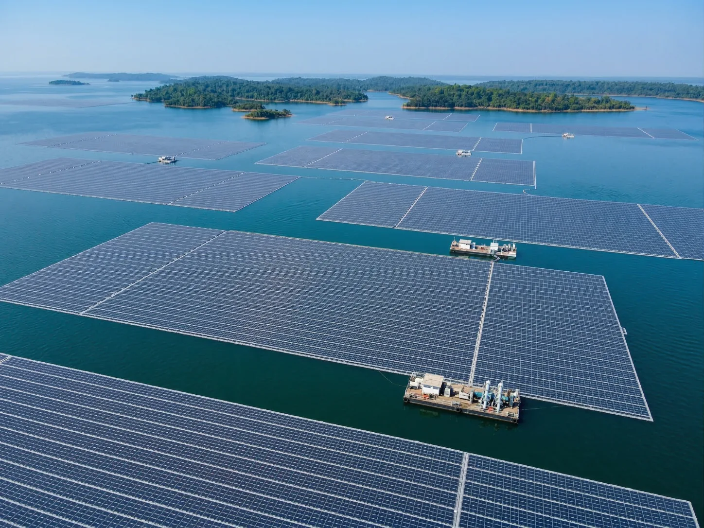
| Omkareshwar – AMP Energy | 140 MWp | Madhya Pradesh | 2024 |
| Omkareshwar – Tata Power | 126 MWp | Madhya Pradesh | 2024 |
| BPCL Kochi | 10 MWp | Kerala | 2024 |
| GVREL Tilaiya | 219 MWp | Jharkhand | 2026 |
| SECI Getalsud | 126 MWp | Jharkhand | 2026 |
| Panchet Dam | 43 MWp | Jharkhand | Ongoing |
| GAIL Pata | 24.3 MWp | Uttar Pradesh | Ongoing |
| ONGC Hazira | 13 MWp | Gujarat | Under development |
| Other installations across our portfolio | 60.7+ MWp | India | Delivered and active |
The scale, geography, and water-body behaviour of these projects vary. Each has contributed to our current approach to the survey, design, production, installation, and commissioning.
1. The Reservoir Is the First Component We Design Around
Our engineering doesn't begin with floats or modules. It begins with the reservoir.
A reservoir is a dynamic operating environment with underwater contours, changing water levels, waves, currents, sediment, and established patterns of use. These conditions determine the placement of the plant, movement of the plant, and how it should be attached.
Before finalising a layout, we study:
- Bathymetry and water depth
- Seasonal and operational water-level variation
- Wind direction, fetch, and wave behaviour
- Reservoir-bed characteristics
- Shoreline geometry and launching access
- Water quality and material exposure
- Navigation and reservoir-operation zones
Usable surface area is not the same size as a usable reservoir, and two reservoirs that are the same size will seldom need the same design. One reservoir may be suitable for simple bank anchoring. Another might require submerged deadblocks, longer mooring lines, or multiple installation fronts.
That's why we don't treat bathymetric surveys, wind-wave studies, and water-level analysis as mere formalities before construction. Improved reservoir data leads to improved array geometry, mooring design, planning of cable routing, and installation for Floating Solar Projects.
2. Mooring Cannot Be Added After the Floating Layout
Of the lessons we have learned, one of the most obvious is that the mooring system and floating layout should be designed in tandem.
We have employed deadblocks, piles, and rock bolts in our projects. The pile anchoring method was used at Simhadri. Deadblock systems were used in Ramagundam, Kawas, and Omkareshwar projects, and rock bolts in the Dalmia Cement project.
The challenge is that the anchoring solution must change as site conditions change.
| Site condition | Direct design effect |
|---|---|
| Water-level range | Mooring length, tension and array movement |
| Wind and wave loads | Anchor reactions and load distribution |
| Bathymetry | Anchor placement and line geometry |
| Reservoir-bed condition | Anchor selection and installation method |
| Array dimensions | Mooring-point quantity and force distribution |
| Shore geometry | Bank access, launching, and cable transitions |
A good mooring design serves not only to keep the plant in place, but also to ensure the stability of the mooring system. It operates throughout the entire operating range of the reservoir and will not interfere with electrical cables, access corridors or maintenance operations.
When designing at a utility scale, even a minor design assumption is replicated hundreds of times along lines and at connections. This multiplication of design assumptions makes it essential to integrate mooring engineering into the layout process from the very beginning of Floating Solar Projects.
3. Standardise the Product, Customise the Plant
Manufacturing has increased to a level of over 550 MW per year. To achieve this scale, repeatability of components, controlled processes, dimensional consistency, and disciplined quality checks are required.
But we don't make the same plants.
The product platform may be standardised, while the system surrounding it must be flexible. With project conditions, the dimensions of the islands, arrangement of the modules, freeboard, access routes, mooring geometry, and placement of inverters and cable transitions all vary.
Customising every individual component only adds unnecessary complexity. Designing every plant from scratch for each reservoir creates greater engineering complexity.
We standardise what can be repeated and customise what each water body requires.
This balance enables us to produce efficiently without forcing the reservoir into a pre-designed mould.
4. Most Difficult Problems Appear Between Engineering Packages
Structural, electrical, civil, hydrological, marine, manufacturing, and grid-integration disciplines all come together in a floating solar project.
The most important issues are typically located at the intersections of these disciplines:
- A change in module dimensions affects float loading and island geometry.
- A larger island changes mooring forces and electrical block sizes.
- Moving an inverter alters cable lengths, platform loading, and access.
- Relocating an anchor can obstruct an electrical corridor.
- Changing the shore landing affects launching and grid evacuation.
- Revising a walkway influences buoyancy, maintenance, and module density.
As capacity grows, so do these relationships. The larger a plant, the more islands, floats, joints, cables, terminations, anchors, and contractor handovers it will have.
As projects scale up, fragmentation becomes more apparent.
We have responded by coordinating shared design inputs earlier, controlling revisions more tightly, and reviewing the entire system whenever any package changes. If a solution works well for one contractor but creates difficulties for three others, it isn't an efficient solution. This integrated approach has become one of the most valuable lessons from delivering Floating Solar Projects.
5. A Good Design Must Also Be Buildable
A competent layout is worth little if it can't be efficiently assembled, launched, and positioned at the project site.
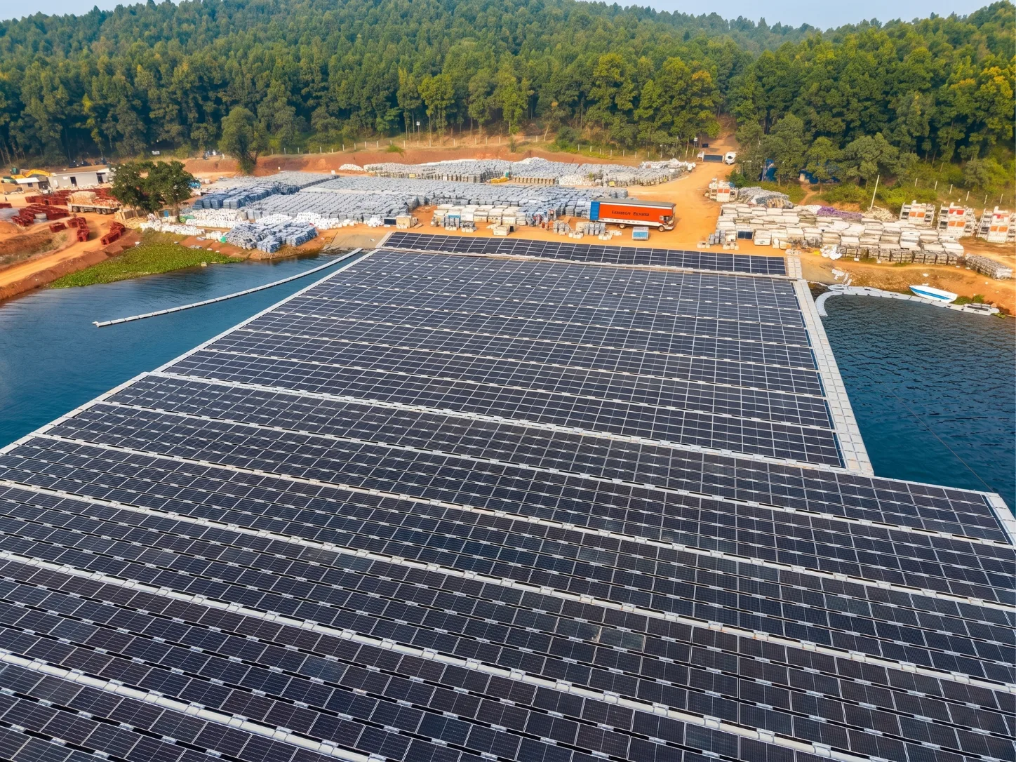
Installation is a large-scale logistical effort at projects such as Ramagundam and Omkareshwar. Thousands of parts need to be delivered in the proper order to the assembly front. The preparation and installation of assemblies and modules, the launching, towing, and anchoring, and the electrical work need not interfere with each other. Efficient execution is a defining requirement for large Floating Solar Projects.
Buildability begins with asking practical questions:
- Where will floats and modules be stored?
- How many assembly fronts can the shoreline support?
- Is the water deep enough for launching?
- Where will completed islands wait before towing?
- How will boats and workers move through the site?
- Can cable drums and heavy equipment reach the shore?
- How will reservoir operations affect the installation programme?
Earlier, we learned to involve execution teams in the design process. They influence island size, towing paths, temporary mooring locations, material movement, and the assembly sequence.
The best time to solve an installation issue is before work begins on the water.
6. Electrical Systems Must Move Without Losing Integrity
Floating solar is a power generation platform that connects floating infrastructure to fixed electrical infrastructure on land. This transition requires a cable design that accommodates both floating and fixed infrastructure.
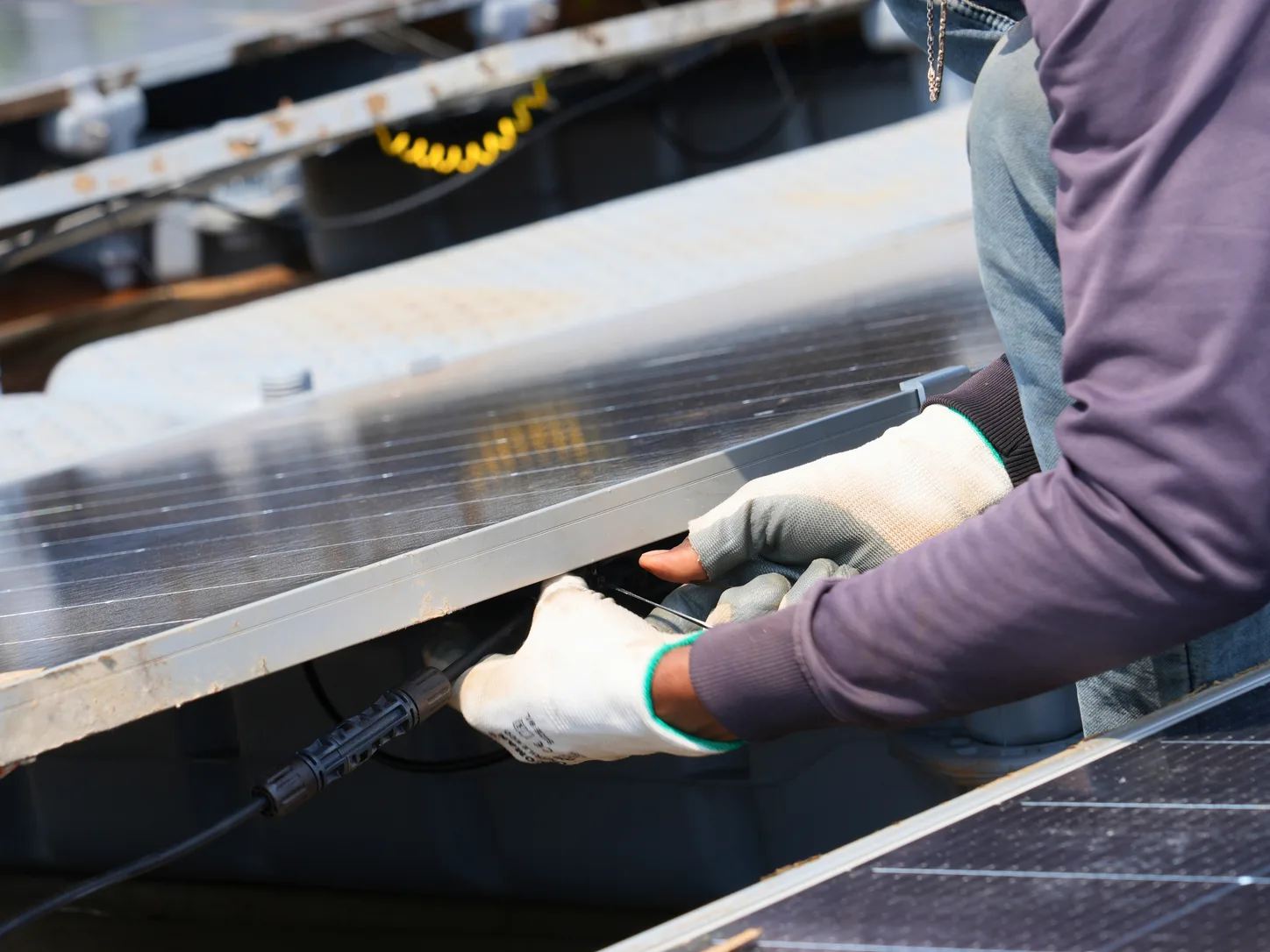
Cables bend, stretch, and reposition repeatedly due to water-level fluctuations and array movement. Support intervals, transition loops, strain reliefs, and shore landings, therefore, must be coordinated with the mooring arrangement.
Over-constriction transfers mechanical forces to the cable terminations. Uncontrolled slack can lead to rubbing, immersion, and inspection issues. The right solution allows controlled cable movement while protecting the cable throughout the reservoir's operating range.
The availability of plants is also influenced by electrical architecture. The amount of generation lost during maintenance or isolation depends on inverter placement, feeder design, block size and transformer location.
IEA PVPS identifies movement, moisture, water contact, corrosion, and accessibility as key factors affecting FPV reliability. These conditions are not treated as exceptions to normal solar practices, but rather addressed as a part of electrical engineering in Floating Solar Projects.
7. Maintenance Access Must Be Designed Before Module Density
Maximum module coverage may appear efficient on a drawing. That advantage is quickly lost during operation if the equipment becomes difficult to access.
There should be clear paths to modules, connectors, combiner boxes, cables, inverters and mooring interfaces for technicians. They also require space to perform work and an efficient way to replace defective parts.
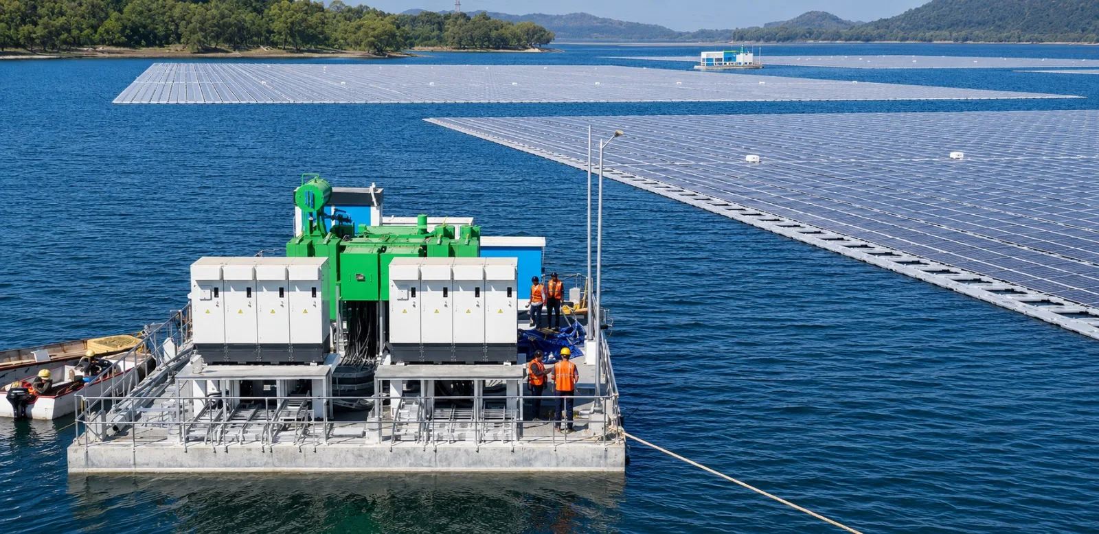
We have designed our walkway system and ferrocement utility barge based on this requirement. Stable platforms for inverters, switchgear, and monitoring equipment are provided on a utility barge. Modular walkways provide inspection and maintenance of the plant.
All layouts have to address three questions:
- How will technicians reach the component?
- Where will they stand while working?
- How will the component be removed and replaced?
A high-performing plant is not simply one that fits more modules on the available water. It remains inspectable, repairable, and operational throughout its design life, which is essential for successful Floating Solar Projects.
8. Commissioning Must Capture the Plant's Starting Condition
Commissioning is not just the point at which a project starts supplying electricity to the grid. It sets a benchmark for decades of use.
Our commissioning records should include:
- Electrical readings and insulation-resistance results
- Mooring positions and line conditions
- Anchor coordinates
- Cable-loop and shore-transition geometry
- As-built drawings
- Equipment identification
- Photographs of critical connections
The records enable future inspection teams to identify movement, wear, and changes before they become significant issues.
The industry needs more consistent, long-term floating solar data. Every commissioned plant provides an opportunity to improve the next one, provided that its starting condition and operating history are properly recorded for future projects.
Building the Next Gigawatt
So far, our first 1 GW+ has taken us to industrial water bodies, thermal power reservoirs, and large hydropower-related projects. Our completed projects range from a few megawatts to installations exceeding 100 MW.
This experience has strengthened our approach to delivering Floating Solar Projects across a wide range of applications.
The next generation of plants will be bigger, more exposed, and more involved with hydropower assets, industrial facilities, and transmission infrastructure. Delivering them will require repeatable manufacturing, site-specific engineering, construction-focused thinking, and greater operational feedback.
To us, the water isn't just the place where the solar plant is located. It is the environment that shapes the entire plant and forms the foundation of successful projects.