In a floating solar project, the array is not the final stage of the system. Electricity must still travel from thousands of floating modules to the shore, pass through transformers and switchgear, and enter the grid at the approved point of interconnection. A well-planned Floating Solar Grid Infrastructure ensures this entire process operates safely and efficiently.
This journey becomes even more challenging when the reservoir is located in a remote area.
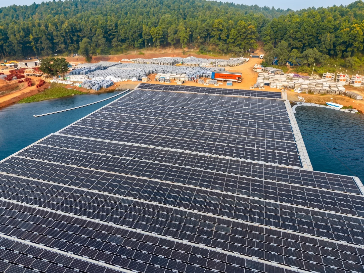
A large water body could have tremendous generation potential, with the closest substation being unable to accommodate it. The shortest transmission route can be through forests, unstable terrain, or inaccessible areas. Shore conditions may complicate cable landing, while weak communication networks can delay fault detection and response.
At Floatex Solar, we see grid evacuation as part of the plant, not as infrastructure to be installed after designing the floating system.
The Complete Route From Water to Grid
Grid evacuation begins at the module and ends only when electricity enters the utility network under the required voltage, protection, and operating conditions.
| System stage | Primary function | Main engineering focus |
|---|---|---|
| Module strings | Collect DC generation | Connectors, isolation, and cable support |
| Array collection | Aggregate floating blocks | Feeder loading, losses, and fault isolation |
| Water crossing | Carry power across moving infrastructure | Flexibility, abrasion, and strain relief |
| Shore landing | Connect the moving array to the fixed land | Water-level range, erosion, and protection |
| Inverter and transformer | Convert and step up power | Location, access, cooling, and replacement |
| Project substation | Protect, meter, and control output | Switchgear, SCADA, and reactive power |
| Evacuation line | Carry power to the utility network | Route, terrain, approvals, and accessibility |
| Grid connection | Transfer electricity to the network | Export limit, protection, and communication |
Each phase is interdependent on the other. Changes in the size of a floating island also affect feeder loading. Relocating an inverter changes the required cable length. Moving the shore landing will alter the transmission route and substation location.
A Nearby Substation Does Not Guarantee Grid Capacity
Distance is only one of the factors for grid feasibility.
The nearest substation might be at the wrong voltage, may not have a spare bay, or may be behind a restricted transmission corridor. The existing transformer may already be operating at capacity. The network might also need reactive-power support, protection upgrades, or a separate evacuation line before accepting new generation.
The first grid assessment needs to be carried out before the project is developed, and it should include. Early grid assessment must establish:
- Permitted export capacity
- Connection voltage
- Available transformer and bay capacity
- Required network augmentation
- Protection and metering requirements
- Communication with the load-despatch system
- Responsibility for each connecting asset
- Schedule for energisation
This evaluation may, in itself, alter the project capacity. It is possible that initially the network permits an export lower than 150 MWp, but that the array can be accommodated physically on a reservoir. The plant design, inverter configuration, and commercial model should be based on the capacity that can actually be connected to the grid through robust Floating Solar Grid Infrastructure.
India's CEA transmission-planning criteria specify that system studies must be conducted with realistic system conditions, considering renewable integration. Therefore, grid evacuation planning should begin during site selection rather than after the module layout has been defined.
Cable Engineering Must Account for Continuous Movement
Cables on floating plants operate under different conditions from those installed on fixed terrestrial structures.
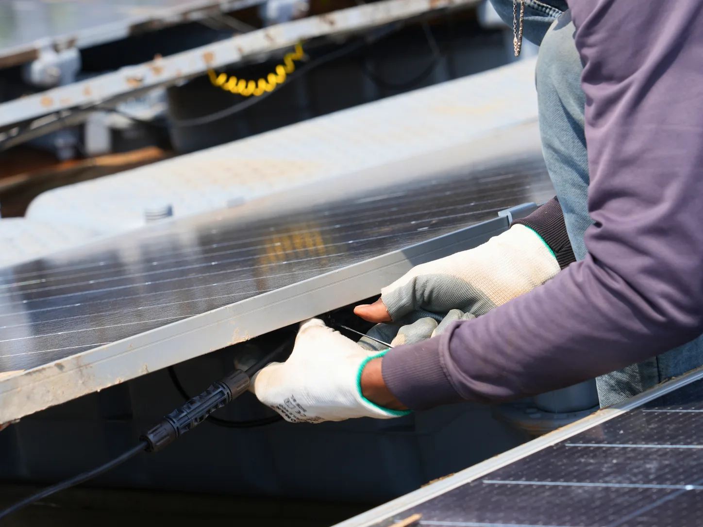
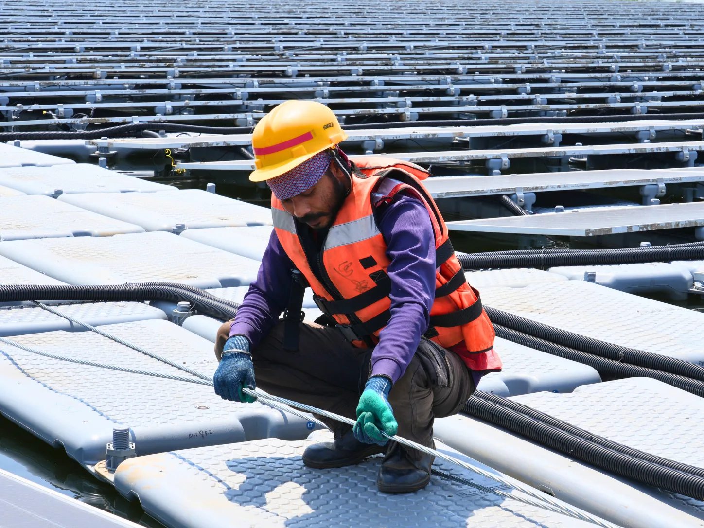
Floating islands move in response to wind, waves, water currents, and changing water levels. The surrounding sections may also be moving in other ways, causing cables that span between sections to be placed under repeated bending and tension.
Our cable design takes care of:
- Minimum bending radius
- Cyclic movement and fatigue
- Buoyancy and support spacing
- Abrasion at contact points
- Strain relief at glands and terminations
- Interaction with mooring lines
- Power and communication cable separation
- Inspection and repair access
- Maximum reservoir drawdown and flood levels
It's not just a matter of adding slack. If there is insufficient clearance, mechanical loads will be transferred into terminations. Avoid excess tension so that cables do not rub, come into contact with water, or come into contact with nearby components. For the flexible sections, controlled geometry and support points are required.
The IEA PVPS floating-PV review identifies movement, moisture, corrosion, and water contact as the major reliability factors affecting floating electrical systems. These factors are addressed during the original cable layout design rather than being left for site adjustments, strengthening the long-term reliability of the Floating Solar Grid Infrastructure.
The Shore Landing Is a Critical Transition
The shore landing links two distinct systems: a moving floating system and a fixed land-based system. As a key component of Floating Solar Grid Infrastructure, the shore landing must ensure a reliable transition between these two environments.
The design should apply to the entire range of water levels. A cable route that works at the normal water level can become stretched as water levels drop, submerged during flooding, or exposed to erosion near the bank.
The transition can take the form of flexible cable loops, support structures, protected trenches, transition pits, and erosion-control measures.
The site chosen should also not be obstructed by any of the following:
- Mooring lines
- Boat routes
- Array-towing paths
- Reservoir debris
- Public-access areas
- Flood-affected ground
- Shoreline maintenance activity
If the landing position is poorly chosen, it will cause problems in the floating layout, electrical system, and transmission path. We therefore consider it to be a designed interface, rather than just a cable that plugs into the land.
Equipment Location Determines Maintainability
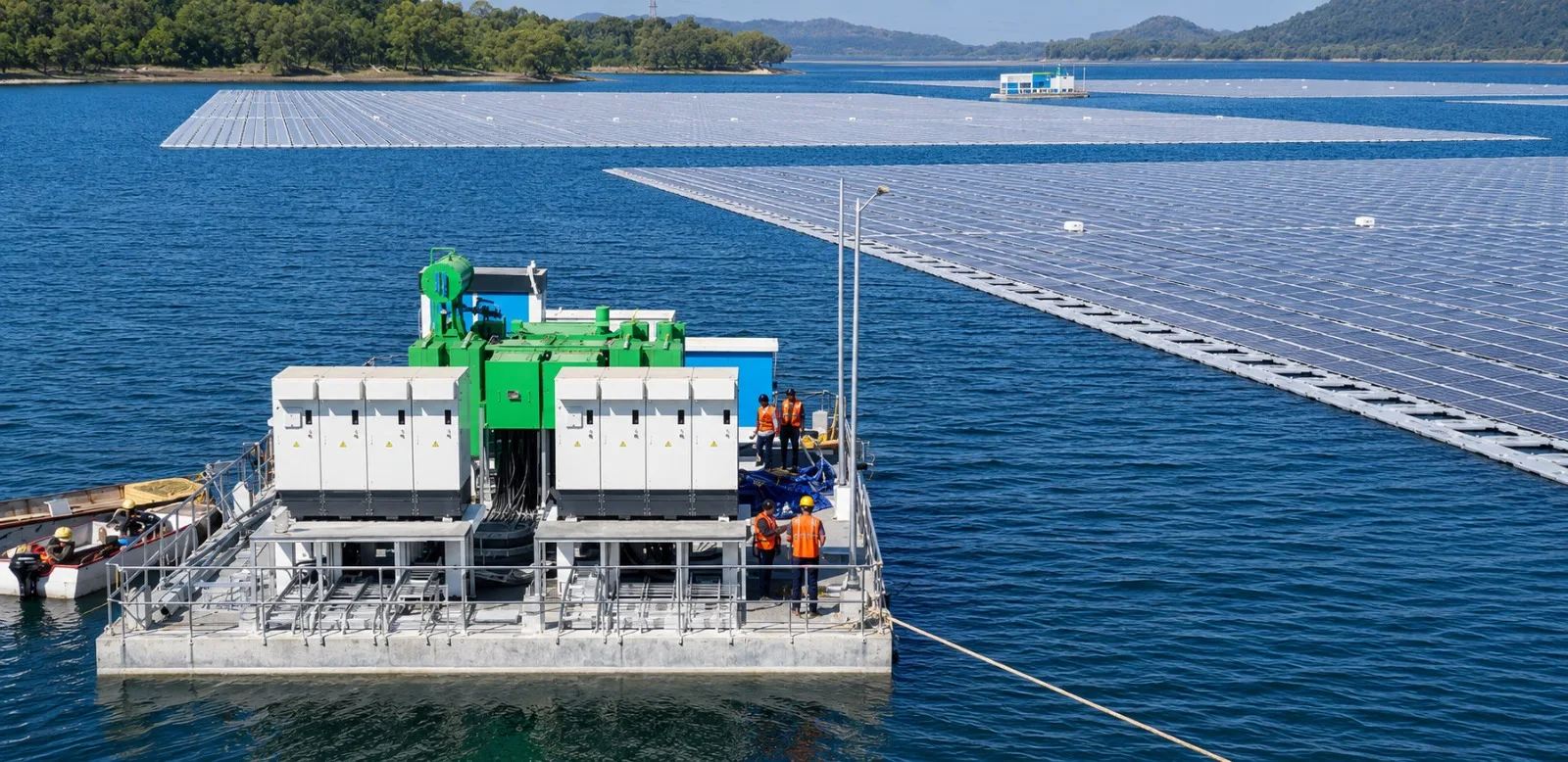
Inverters and transformers may be located in floating utility platforms, onshore, or in a hybrid configuration.
Locating equipment closer to the array reduces cable lengths, but the platform must also support equipment weight, maintenance loads, cable forces, and equipment replacement activities. The use of onshore equipment makes maintenance of heavy equipment easier, but also makes some of the collection circuits longer.
Floatex Solar designs and manufactures ferrocement utility barges that provide stable platforms for inverters, switchgear, and monitoring systems. They are designed to provide structural capacity, maintenance access, electrical service routing, and space for equipment replacement, strengthening the overall Floating Solar Grid Infrastructure.
The project substation then carries out a few vital roles:
- Feeder switching and fault isolation
- Voltage transformation
- Protection and metering
- Reactive-power control
- SCADA and communication
- Auxiliary power supply
- Grid-code compliance
The system arrangement determines how much generation will be lost if a feeder, transformer, or bus section becomes unavailable.
Remote Transmission Routes Demand Lifecycle Access
For remote reservoirs, the evacuation line is often the longest and most complex infrastructure component of the project.
The path could extend through forests, fields, canals, rivers, roads, railways, or unstable slopes. Not every line on a map is necessarily the best line to follow.
We not only determine if the line can be built, but also if it can be inspected and repaired during the plant's service life. Permanent access is important for vegetation management, tower inspection, cable joint repair, and replacement equipment movement.
A construction road used for transporting equipment during the EPC phase is not, in itself, deemed fit for emergency access during the monsoon.
Existing Hydropower Infrastructure Still Requires Integration
Switchyards, transformers, roads, and transmission corridors are already present in hydropower reservoirs. These assets can accelerate floating solar development if the shared infrastructure is designed as a single operating system.
Both solar and hydropower generation can export at the same time. Combined operating scenarios of common transformers and outgoing lines must therefore be accommodated. Existing infrastructure delivers the greatest value when capacity, operational control, and asset ownership are aligned from the outset, allowing the Floating Solar Grid Infrastructure to operate efficiently alongside hydropower assets.
The Plant Is Only Complete When Its Power Can Leave
A floating array can be completely installed and operational while the evacuation line, utility bay, and/or protection system is still being installed. In that state, the installed capacity is not yet deliverable electricity.
At Floatex Solar, we combine the study of reservoirs, floating system design, cable routing, utility barges, electrical installation, and grid tie-in into one engineering process.
The reservoir determines where generation begins. Whether that generation can be delivered to the grid depends on the grid evacuation system. A floating solar project needs to be designed to meet both requirements, with Floating Solar Grid Infrastructure ensuring that power can be reliably delivered from the reservoir to the utility network.